
Home / Central Advanced Earthquake Engineering Lab. / Centrifuge and Physical Modeling Laboratory
Due to the reduced stress levels applied to scaled-down models compared to real structures, their behavior can significantly differ. Using a centrifuge places the model in a gravitational field higher than Earth’s natural gravity, increasing weight-induced stresses to realistic levels and making the model’s behavior closely resemble actual behavior. By applying appropriate similarity ratios, the real structural behavior is inferred from the small-scale model.
Today, leveraging modern technical knowledge and domestic scientific and technical capabilities, the centrifuge device at the International Institute of Earthquake Engineering and Seismology is ready to support research projects and collaborate with industry to meet national needs.
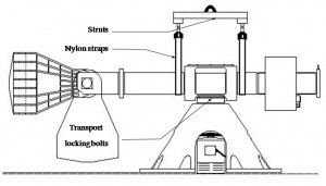
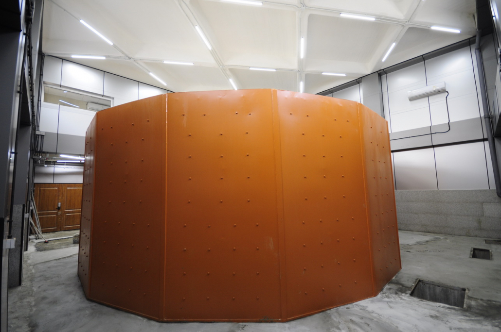
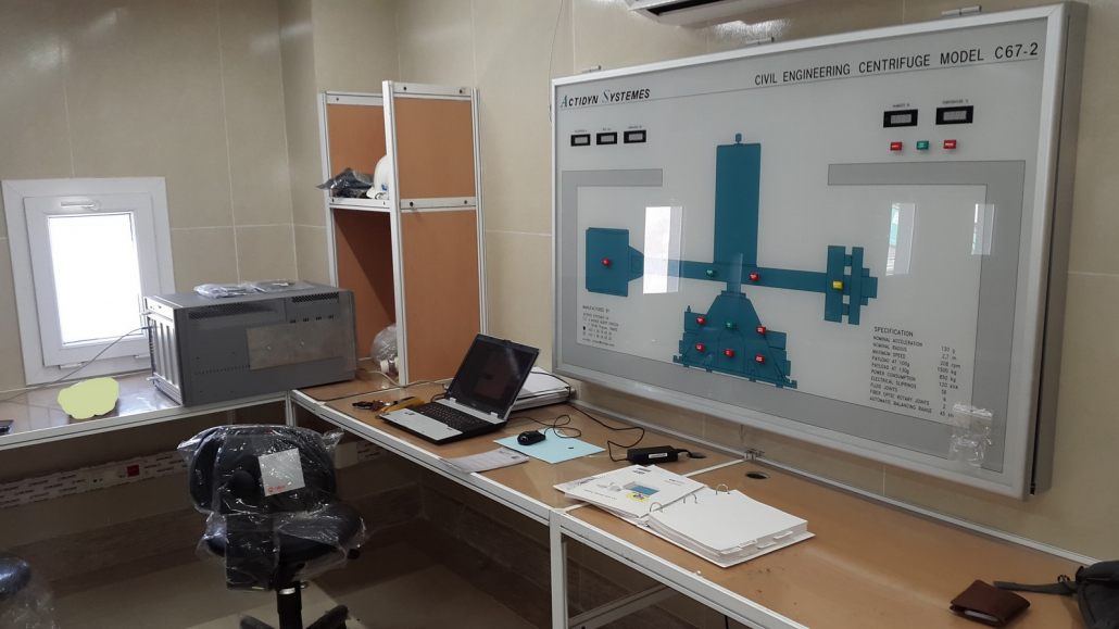
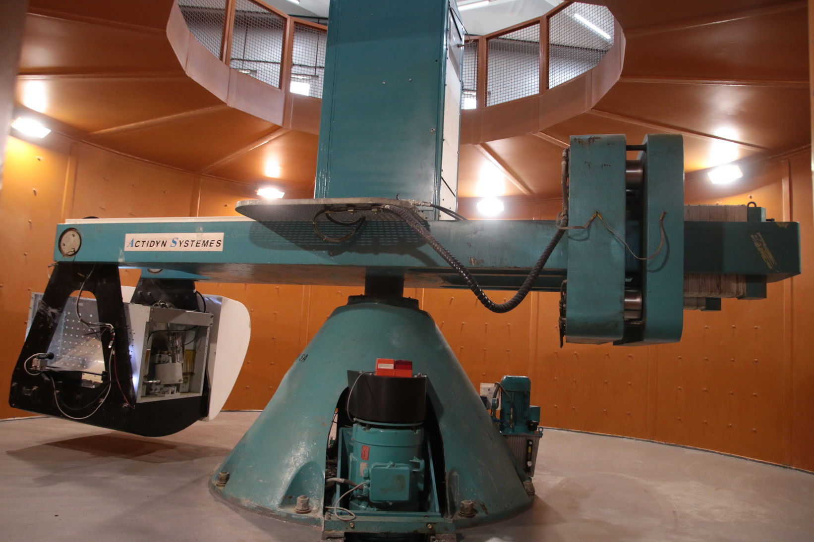
In physical modeling, the centrifuge device holds a prominent position. Only a few countries possess the technology to build such devices. The centrifuge in this laboratory was purchased in 2002 from ACTIDYN, France. It is currently installed in the advanced earthquake engineering laboratory. Due to lack of cooperation from the manufacturer, it was fully commissioned by domestic experts and has successfully completed several research projects. This places the institute among the few centers equipped with such advanced technology.
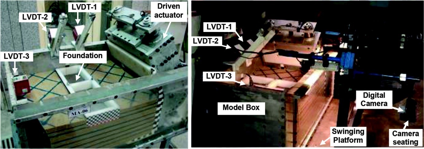
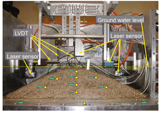
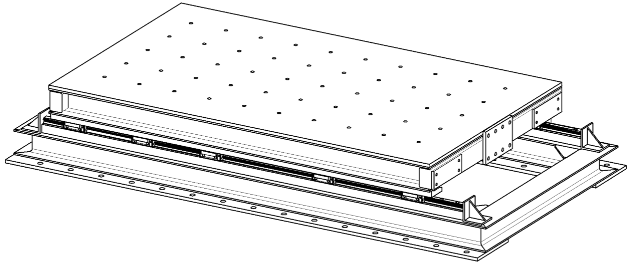
Boundary conditions in physical modeling of seismic geotechnical problems significantly affect results. To minimize adverse boundary effects, a Laminar Box is used. It simulates soil column movement during earthquakes and is mounted on a compatible Shaking Table.
Centrifuge Device
Laminar Box Established on Shaking Table
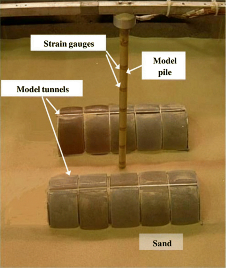
The geotechnical centrifuge has wide applications in geotechnical engineering, including:
|
Project Title |
Lead Researcher | Loading Equipment |
| Study of dip-slip faulting effects on tunnel damage and mitigation strategies | Kazem Jafari, Seyed Mojtaba Mousavi | Centrifuge |
| Experimental study of surface faulting effects on buried pipelines | Kazem Jafari, Seyed Mojtaba Mousavi | Centrifuge |
|
Project Title |
Lead Researcher | Loading Equipment |
| Seismic response and permanent settlement of shallow foundations on sand: physical modeling in laminar box | Yaser Jafarian | Laminar Box |
| Performance improvement of shallow foundations on loose granular soils with superstructure using flexible container on Shaking Table | Yaser Jafarian | Laminar Box |
| Performance improvement of shallow foundations on granular soils using flexible container on Shaking Table | Yaser Jafarian | Laminar Box |
|
Project Title |
Lead Researcher | Loading Equipment |
| Evaluation of forces on piles in slopes prone to liquefaction-induced lateral spreading | Yaser Jafarian | Laminar Box |
| Name | Position | Department / Area of activity | Phone | |
|---|---|---|---|---|
| Head of Geotechnical Eng. Laboratory, Head of Centrifuge Laboratory, Head of Geotechnical Earthquake Engineering Department | Geotechnical Earthquake Engineering | jalili@iiees.ac.ir | 565 |
| Name | Position | Area of activity / Department | Phone | |
|---|---|---|---|---|
| Saeed ghazinezhad | Expert | Geotecnical Engineering Laboratory, Centrifuge and Physical Modeling Laboratory | s.ghazinezhad@iiees.ac.ir | 124 |
Specifications of the centrifuge at the International Institute of Earthquake Engineering and Seismology are as follows:
It enables physical modeling of geotechnical structures or soil-structure interaction. Features include:
Accessories include:
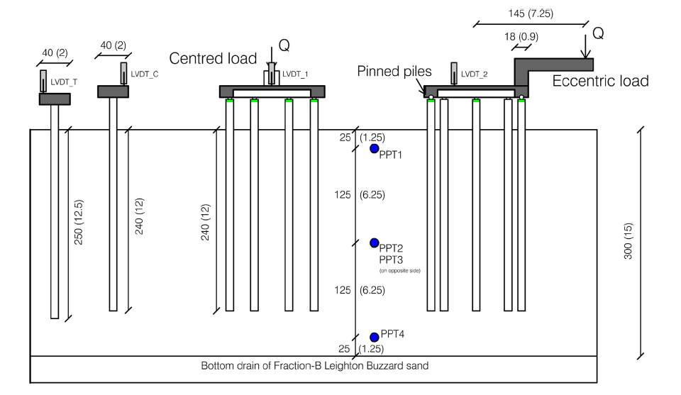
Pile loading tests are mainly conducted during the design phase to ensure safety and monitor execution. These tests assess pile capacity and behavior under vertical and lateral loads using:
These tests determine ultimate pile capacity, allowable settlement, integrity, and calibrate theoretical design methods. They are crucial for large projects like bridge foundations, coastal structures, tall towers, and industrial facilities.
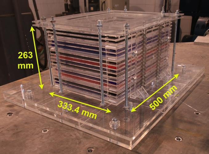
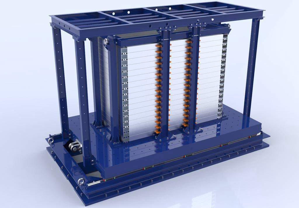
Built to test and refine the design of the large-scale box. Dimensions:
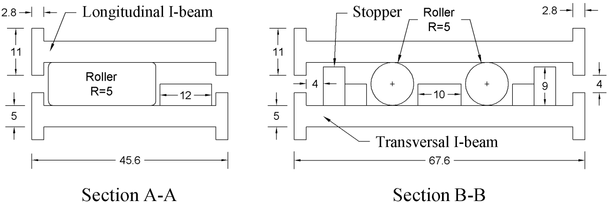
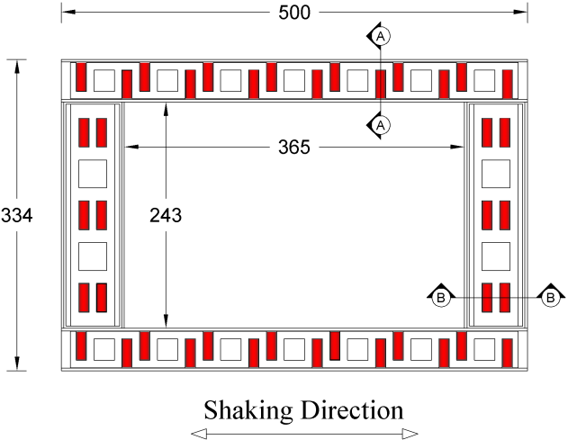
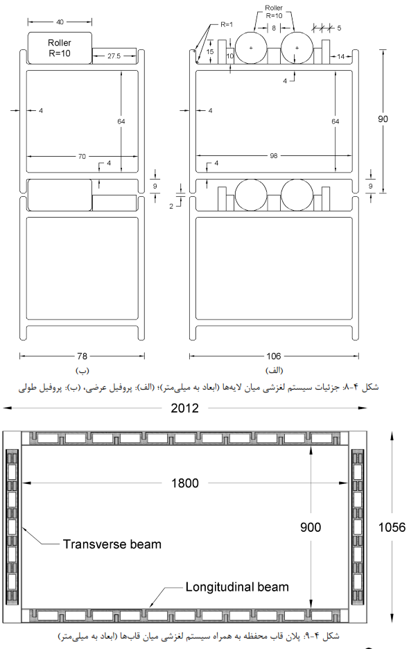
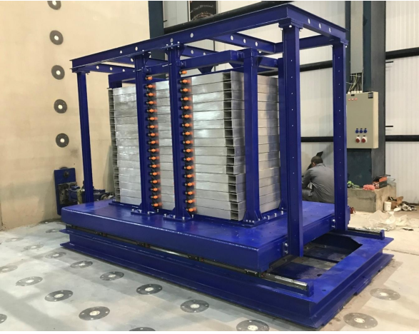
The medium-scale laminar shear box consists of 17 rectangular aluminum alloy frames with internal dimensions of 1800 mm long and 900 mm wide, and when all the frames are stacked, it will have a height of 1577 mm. Roller bearings that are placed between the frames and separate them allow the frames to move on top of each other in the longitudinal direction with minimal frictional resistance. Considering a relative displacement of 28 mm between layers, the absolute displacement of the uppermost layer reaches 476 mm, which is equal to a maximum shear strain of 30%, which is suitable for modeling phenomena such as liquefaction and landslides in which large strains occur.
The medium-scaled shaking table system is designed for easy installation on a strong floor and removal when space is limited. It is medium-scale: